IASPEI Seismic Format (ISF)
ISF is the IASPEI approved standard format for the exchange of parametric seismological data (hypocentres, magnitudes, phase arrivals, moment tensors, etc.).
It was adopted as standard in August 2001 by IASPEI's Commission on Seismic Observation and Interpretation at the Scientific Assembly in Hanoi, Vietnam. The format
is an extenstion of IMS1.0.
Bulletins which use ISF comprise of a series of data blocks. These include a bulletin title block, an event title block, an origin block, a magnitude block, a phase
block, etc. An important extension of IMS1.0 is the ability to add comments with keywords refering to specific parametric data. The keywords include PRIME
(to designate a prime origin of a hypocentre), CENTROID (to indicate the centroid origin), MOMTENS (moment tensor solution), FAULT_PLANE
(fault plane solution), PRINAX (principal axes), PARAM (an origin parameter e.g. hypocentre depth determined by depth phases).
ISF 2 (IASPEI Seismic bulletin Format)
There has been a need to add a number of data types to ISF 1 for sometime, this has lead to the development of ISF 2. The format is an extension of ISF 1 as all additional data is in extensions to the existing ISF 1 formats. The changes chiefly are improved data attribution through extended station details and channel information for phases and amplitude.
ISF 2.1 (IASPEI Seismic bulletin Format)
ISF version 2.1 is a development of version 2 with additional data fields for the station imformation and the extension of more ID fields to 11 digits.
The full documentation of the different versions is available to download:
Source code (in Fortran and C) is provided to read and write ISF 1 data for BULLETIN and ARRIVAL:GROUPED data types:
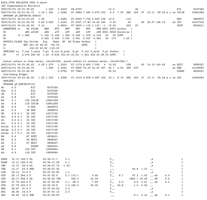
Example of an ISF Bulletin for a single event (N.B. the data has been modified for illustration purposes) displaying the multiple data blocks available:
IMS1.0/ISF Summary
The following summary provides the formatting required to read or write ISF files for three different data types: Bulletin data; Station data; Arrival data. Please refer to the full documentation for all the available data types and subtypes.
Bulletins are composed of events, origins and associated arrival information and may include a 'bulletin title', an 'event title', an 'origin block', a 'magnitude sub-block', a 'comment sub-block' and 'phase block'. In addition there are ISF extensions to provide additional data (e.g. moment tensors, fault plane solutions, etc.)
| Record | Position | Format | Description |
| 1 | 1-136 | a136 | bulletin title |
| Record | Position | Format | Description |
| 1 | 1-5 | a5 | Event |
| | 7-14 | a8 | event identification number |
| | 16-80 | a65 | geographic region |
| Record | Position | Format | Description |
| Origin Sub-block | | |
| 1 | 4-7 | a4 | Date |
| (header) | 15-18 | a4 | Time |
| | 27-29 | a3 | Err |
| | 33-35 | a3 | RMS |
| | 37-44 | a8 | Latitude |
| | 46-54 | a9 | Longitude |
| | 57-60 | a4 | Smaj |
| | 63-66 | a4 | Smin |
| | 69-70 | a2 | Az |
| | 72-76 | a5 | Depth |
| | 80-82 | a3 | Err |
| | 84-87 | a4 | Ndef |
| | 89-92 | a4 | Nsta |
| | 94-96 | a3 | Gap |
| | 99-103 | a5 | mdist |
| | 106-110 | a5 | Mdist |
| | 112-115 | a4 | Qual |
| | 19-124 | a6 | Author |
| | 131-136 | a6 | OrigID |
| Record | Position | Format | Description |
| | 1-10 | i4,a1,i2,a1,i2 | epicenter date (yyyy/mm/dd) |
| | 12-22 | i2,a1,i2,a1,f5.2 | epicenter time (hh:mm:ss.ss) |
| | 23 | a1 | fixed flag (f = fixed origin time solution, blank if not a fixed origin time) |
| | 25-29 | f5.2 | origin time error (seconds; blank if fixed origin time) |
| | 31-35 | f5.2 | root mean square of time residuals (seconds) |
| | 37-44 | f8.4 | latitude (negative for South) |
| | 46-54 | f9.4 | longitude (negative for West) |
| | 55 | a1 | fixed flag (f = fixed epicenter solution, blank if not a fixed epicenter solution) |
| | 56-60 | f5.1 | semi-major axis of 90% ellipse or its estimate (km, blank if fixed epicenter) |
| | 62-66 | f5.1 | semi-minor axis of 90% ellipse or its estimate (km, blank if fixed epicenter) |
| | 68-70 | i3 | strike (0 <= x <= 360) of error ellipse clock-wise from North (degrees) |
| | 72-76 | f5.1 | depth (km) |
| | 77 | a1 | fixed flag (f = fixed depth solution, d = depth phases, blank if not a fixed depth) |
| | 79-82 | f4.1 | depth error 90% (km; blank if fixed depth) |
| | 84-87 | i4 | number of defining phases |
| | 89-92 | i4 | number of defining stations |
| | 94-96 | i3 | gap in azimuth coverage (degrees) |
| | 98-103 | f6.2 | distance to closest station (degrees) |
| | 105-110 | f6.2 | distance to furthest station (degrees) |
| | 112 | a1 | analysis type: (a = automatic, m = manual, g = guess) |
| | 114 | a1 | location method: (i = inversion, p = pattern recognition, g = ground truth, o = other) |
| | 116-117 | a2 | event type:
|
| | | | uk = unknown |
| | | | de = damaging earthquake ( Not standard IMS ) |
| | | | fe = felt earthquake ( Not standard IMS ) |
| | | | ke = known earthquake |
| | | | se = suspected earthquake |
| | | | kr = known rockburst |
| | | | sr = suspected rockburst |
| | | | ki = known induced event |
| | | | si = suspected induced event |
| | | | km = known mine expl. |
| | | | sm = suspected mine expl. |
| | | | kh = known chemical expl. ( Not standard IMS ) |
| | | | sh = suspected chemical expl. ( Not standard IMS ) |
| | | | kx = known experimental expl. |
| | | | sx = suspected experimental expl. |
| | | | kn = known nuclear expl. |
| | | | sn = suspected nuclear explosion |
| | | | ls = landslide |
| | 119-127 | a9 | author of the origin |
| | 129-136 | a8 | origin identification |
| Record | Position | Format | Description |
| Magnitude Sub-block | | |
| 1 | 1-9 | a9 | Magnitude |
| (header) | 12-14 | a3 | Err |
| | 16-19 | a4 | Nsta |
| | 21-26 | a6 | Author |
| | 33-38 | a6 | OrigID |
| 2-n | 1-5 | a5 | magnitude type (mb, Ms, ML, mbmle, msmle) |
| (data) | 6 | a1 | min max indicator (<, >, or blank) |
| | 7-10 | f4.1 | magnitude value |
| | 12-14 | f3.1 | standard magnitude error |
| | 16-19 | i4 | number of stations used to calculate magni-tude |
| | 21-29 | a9 | author of the origin |
| | 31-38 | a8 | origin identification |
| Record | Position | Format | Description |
| Comment Sub-block | | |
| 1 | 2 | a1 | ( |
| | 3-M | a(M-2) | comment |
| | M+1 | a1 | ) |
| Record | Position | Format | Description |
| 1 | 1-3 | a3 | Sta |
| (header) | 9-12 | a4 | Dist |
| | 15-18 | a4 | EvAz |
| | 20-24 | a5 | Phase |
| | 33-36 | a4 | Time |
| | 43-46 | a4 | TRes |
| | 49-52 | a4 | Azim |
| | 54-58 | a5 | AzRes |
| | 62-65 | a4 | Slow |
| | 69-72 | a4 | SRes |
| | 74-76 | a3 | Def |
| | 80-82 | a3 | SNR |
| | 90-92 | a3 | Amp |
| | 96-98 | a3 | Per |
| | 100-103 | a4 | Qual |
| | 105-113 | a9 | Magnitude |
| | 118-122 | a5 | ArrID |
| Record | Position | Format | Description |
| 2-n | 1-5 | a5 | station code |
| (data) | 7-12 | f6.2 | station-to-event distance (degrees) |
| | 14-18 | f5.1 | event-to-station azimuth (degrees) |
| | 20-27 | a8 | phase code |
| | 29-40 | i2,a1,i2,a1,f6.3 | arrival time (hh:mm:ss.sss) |
| | 42-46 | f5.1 | time residual (seconds) |
| | 48-52 | f5.1 | observed azimuth (degrees) |
| | 54-58 | f5.1 | azimuth residual (degrees) |
| | 60-65 | f5.1 | observed slowness (seconds/degree) |
| | 67-72 | f5.1 | slowness residual (seconds/degree) |
| | 74 | a1 | time defining flag (T or _) |
| | 75 | a1 | azimuth defining flag (A or _) |
| | 76 | a1 | slowness defining flag (S or _) |
| | 78-82 | f5.1 | signal-to-noise ratio |
| | 84-92 | f9.1 | amplitude (nanometers) |
| | 94-98 | f5.2 | period (seconds) |
| | 100 | a1 | type of pick (a = automatic, m = manual) |
| | 101 | a1 | direction of short period motion (c = compression, d = dilatation, _= null) |
| | 102 | a1 | onset quality (i = impulsive, e = emergent, q = questionable, _ = null) |
| | 104-108 | a5 | magnitude type (mb, Ms, ML, mbmle, msmle) |
| | 109 | a1 | min max indicator (<, >, or blank) |
| | 110-113 | f4.1 | magnitude value |
| | 115-122 | a8 | arrival identification |
top
Each moment tensor report is comprised of two header lines and a variable
number of pairs of data lines. All of the moment tensors in one report are
for the same origin, which precedes the report. Several items are omitted:
"Centroid, since it is presumed to precede in an origin line. "The best
fitting double-couple, since it could follow as a FAULT_PLANE comment.
"Principal axes, since they could follow as a PRINAX comment. "MW,
since it could be included in the magnitude sub-block associated with
the event. Several redundant items are included: "All three diagonal
elements of the moment tensor are included since non-isotropic moment
tensors may be reported occasionally "Scalar moment, fraction CLVD
and their uncertainties are included since these may be the most
frequently used moment tensor parameters.
Table: Formatted Moment Tensor Comment
| Record | Position | Format | Description |
| 1 | 3-10 | a8 | #MOMTENS |
| Header | 12-13 | a2 | sc |
| | 18-19 | | M0 |
| | 21-25 | | fCLVD |
| | 30-32 | | MRR |
| | 37-39 | | MTT |
| | 44-46 | | MPP |
| | 51-53 | | MRT |
| | 58-60 | | MTP |
| | 65-67 | | MPR |
| | 69-72 | | NST1 |
| | 74-77 | | NST2 |
| | 79-84 | | Author |
Record | Position | Format | Description |
| 2 | 3 | a1 | # |
| (header) | 17-19 | a3 | eM0 |
| | 21-25 | a5 | eCLVD |
| | 30-32 | a3 | eRR |
| | 37-39 | a3 | eTT |
| | 44-46 | a3 | ePP |
| | 51-53 | a3 | eRT |
| | 58-60 | a3 | eTP |
| | 65-67 | a3 | ePR |
| | 69-72 | a4 | NCO1 |
| | 74-77 | a4 | NCO2 |
| | 79-86 | a8 | Duration |
Record | Position | Format | Description |
| 3 | 3 | a1 | # |
| (data) | 12-13 | i2 | scale factor (log10 of number by which moment tensor components and their uncertainties must be multiplied to obtain Newton-meters) |
| | 15-19 | f5.3 | scalar seismic moment |
| | 21-25 | f5.3 | fraction of moment released as a compensated linear vector dipole |
| | 27-32 | f6.3 | radial-radial element of moment tensor |
| | 34-39 | f6.3 | theta-theta element of moment tensor |
| | 41-46 | f6.3 | phi-phi element of moment tensor |
| | 48-53 | f6.3 | radial-theta element of moment tensor |
| | 55-60 | f6.3 | theta-phi element of moment tensor |
| | 62-67 | f6.3 | phi-radial element of moment tensor |
| | 69-72 | i4 | number of stations used, type 1 (Body wave for HRVD) |
| | 74-77 | i4 | number of stations used, type 2 (Mantle or Surface wave for HRVD) |
| | 79-87 | a9 | agency that computed the moment tensor |
| Record | Position | Format | Description |
| 4 | 3 | a1 | # |
| (data) | 15-19 | f5.3 | uncertainty of scalar seismic moment |
| | 21-25 | f5.3 | uncertainty of fCLVD |
| | 27-32 | f6.3 | uncertainty of radial-radial element |
| | 34-39 | f6.3 | uncertainty of theta-theta element |
| | 41-46 | f6.3 | uncertainty of phi-phi element |
| | 48-53 | f6.3 | uncertainty of radial-theta element |
| | 55-60 | f6.3 | uncertainty of theta-phi element |
| | 62-67 | f6.3 | uncertainty of phi-radial element |
| | 69-72 | i4 | number of components used, type 1 |
| | 74-77 | i4 | number of components used, type 2 |
| | 79-86 | f8.2 | presumed or computed source duration (seconds) |
top
Either one plane or two may be given.
Table: Fault Plane Solution Origin Comment
| Record | Position | Format | Description |
| 1 | 3-14 | a12 | #FAULT_PLANE |
| (header) | 16-18 | a3 | Typ |
| | 20-25 | a6 | Strike |
| | 29-31 | a3 | Dip |
| | 36-39 | a4 | Rake |
| | 42-44 | a2 | NP |
| | 46-47 | a2 | NS |
| | 49-53 | a5 | Plane |
| | 55-60 | a6 | Author |
Record | Position | Format | Description |
| 2 | 3 | a1 | # first plane, + second plane |
| (data) | 16-18 | a3 | Fault plane solution computed from: |
| | | | FM = first motions |
| | | | BDC = best double couple |
| | 20-25 | f6.3 | Strike of either nodal plane (degrees, 0 to 360) |
| | 27-31 | f5.3 | Dip of the same nodal plane (degrees, 0 to 90) |
| | 33-39 | f7.3 | Rake of slip vector in the described plane (degrees, -180 to +180; required if only one plane is given) |
| | 41-43 | i3 | number of P polarities (not required for type BDC) |
| | 45-47 | i3 | number of S polarisations (not required for type BDC) |
| | 49-53 | a5 | Plane identification: AUXIL = this is the auxiliary plane = neither plane is preferred at the fault |
| | | | FAULT = this is the preferred fault plane |
| | | | AUXIL = this is the auxiliary plane |
| | 55-62 | a8 | agency that computed the fault plane solution (neither required nor paresd for second plane) |
top
Principal axes can be computed from either a moment tensor
or a fault plane solution. A bulletin may include the
principal axes alone, or as well as the moment tensor
or fault plane solution from which they were computed.
Principal values are optional since they may not be
available if the principal axes are computed from a
fault plane solution based on first motions. The error
header and error lines are each optional. ISPF writers
should write the error header if the error data line is
written. ISPF parsers should be able to parse the error
line regardless of whether or not the error header line
is present.
Table: Formatted Principal Axes Origin Comment
| Record | Position | Format | Description |
| 1 | 3-9 | a7 | #PRINAX |
| (header) | 11-12 | a2 | sc |
| | 15-19 | a5 | T_val |
| | 21-26 | a6 | T_azim |
| | 29-32 | a4 | T_pl |
| | 35-39 | a5 | B_val |
| | 41-46 | a6 | B_azim |
| | 49-52 | a4 | B_pl |
| | 55-59 | a5 | P_val |
| | 61-66 | a6 | P_azim |
| | 69-72 | a4 | P_pl |
| | 74-79 | a6 | Author |
Record | Position | Format | Description |
| 2 | 2 | a1 | + |
| (header) | 17-19 | a3 | eTv |
| | 24-26 | a3 | eTa |
| | 30-32 | a3 | eTp |
| | 37-39 | a3 | eBv |
| | 44-46 | a3 | eBa |
| | 49-52 | a3 | eBp |
| | 57-59 | a3 | ePv |
| | 64-66 | a3 | ePa |
| | 70-72 | a3 | ePp |
| | 74-78 | a5 | fCLVD |
Record | Position | Format | Description |
| 3 | 3 | a1 | # |
| (data) | 11-12 | i2 | scale factor (log10 of number by which moment tensor components and their uncertainties must be multiplied to obtain Newton-meters; optional) |
| | 14-19 | f6.3 | largest principal value (optional) |
| | 21-26 | f6.2 | largest principal value axis azimuth |
| | 28-32 | f5.2 | largest principal value axis plunge |
| | 34-39 | f6.3 | middle principal value (optional) |
| | 41-46 | f6.2 | middle principal value axis azimuth |
| | 48-52 | f5.2 | middle principal value axis plunge |
| | 54-59 | f6.3 | smallest principal value (optional) |
| | 61-66 | f6.2 | smallest principal value axis azimuth |
| | 68-72 | f5.2 | smallest principal value axis plunge |
| | 74-81 | a8 | agency that computed the principal axes |
Record | Position | Format | Description |
| 4 | 3 | a1 | # |
| (data) | 15-19 | f5.3 | uncertainty of T principal value (optional) |
| | 22-26 | f5.2 | uncertainty of T axis azimuth |
| | 28-32 | f5.2 | uncertainty of T axis plunge |
| | 35-39 | f5.3 | uncertainty of B principal value (optional) |
| | 42-46 | f5.2 | uncertainty of B axis azimuth |
| | 48-52 | f5.2 | uncertainty of B axis plunge |
| | 55-59 | f5.3 | uncertainty of P principal value (optional) |
| | 62-66 | f5.2 | uncertainty of P axis azimuth |
| | 68-72 | f5.2 | uncertainty of P axis plunge |
| | 74-78 | f5.3 | fraction of the moment release as compensated linear vector dipole (optional) |
top
After the keyword PARAM, each origin parameter comment consists
of a set of names from the MSOP list of earthquake parameters
followed by an equal sign and a value. Spaces are not allowed
before or after the equal sign, but are instead reserved as
a separator between measurements. Units are not given for
the measurements, but specified for each standard measurement
name (e.g., STRESS_DROP must be given in Pascals). Values must
be stated as real numbers including a decimal point and may
include an exponent, indicated by an upper-case E , e.g., 1.0E27.
Table: Formatted Additional Parameter Origin Comment
| Record | Position | Format | Description |
| 1 | 3-8 | a6 | #PARAM |
(data) | 10-89 | a80 | name=VALUE name=VALUE .... |
Table: Preliminary List of Additional Origin Parameters
| Name | Units | Description |
| | STRESS_DROP | Pascals | |
| SCALAR_MOMENT | Newton-meters | |
| SEISMIC_ENERGY | Joules | |
| pP_DEPTH | Kilometers | |
top
Prior to 1996 the ISC bibliography provided a link between events and research papers associated with them.
This data block reproduces the ISC bibliography.
Table: Bibliographic Citations
| Record | Position | Format | Description |
| 1 | 1-4 | a12 | Year |
| (header) | 6-11 | a3 | Volume |
| | 13-17 | a6 | Page1 |
| | 19-23 | a3 | Page2 |
| | 25- | a4 | Journal |
Record | Position | Format | Description |
| 2 | 1-4 | i4 | Year of publication |
| (data) | 6-11 | a6 | Volume |
| | 13-17 | i5 | Start page |
| | 19-23 | i5 | End page |
| | 25-104 | a80 | Journal title |
| Record | Position | Format | Description |
| Comment Sub-block | | |
| 1 | 2-10 | a9 | (#AUTHORS |
| (data) | 11-90 | a80 | Author , author ... author. |
| | 92 | a1 | ) |
| 2-n | 2-3 | a2 | (+ |
| (continuation) | 11-90 | a80 | Author , author ... author. |
| | 92 | a1 | ) |
| Record | Position | Format | Description |
| Comment Sub-block | | |
| 1 | 2-8 | a7 | (#TITLE |
| (data) | 11-90 | a80 | Title. |
| | 92 | a1 | ) |
| 2-n | 2-3 | a2 | (+ |
| (continuation) | 11-90 | a80 | Title |
| | 92 | a1 | ) |
The STATION data type is used to describe the site, location, and dates of operation for stations.
Station block format
| Record | Position | Format | Description |
| 1 | 1-3 | a3 | Net |
| (header) | 15-18 | a3 | Sta |
| | 27-29 | a4 | Type |
| | 33-35 | a8 | Latitude |
| | 37-44 | a9 | Longitude |
| | 46-54 | a9 | Coord Sys |
| | 57-60 | a4 | Elev |
| | 63-66 | a7 | On Date |
| | 63-66 | a8 | Off Date |
| 2-n | 1-9 | a9 | network code |
| (data) | 11-15 | a5 | station code |
| | 17-20 | a4 | 1c = single component |
| | | | 3c = three component |
| | | | hfa = high-frequency array |
| | | | lpa = long-period array |
| | 22-30 | f9.5 | latitude (negative for South) |
| | 32-41 | f10.5 | longitude (negative for West) |
| | 43-54 | a12 | coordinate system (for example, WGS-84) |
| | 56-60 | f5.3 | elevation (km) |
| | 62-71 | i4,a1,i2,a1,i2 | start date of station operation (yyyy/mm/dd) |
| | 73-82 | i4,a1,i2,a1,i2 | end of station operation (yyyy/mm/dd) |
The ARRIVAL data type is divided into five subtypes (automatic, reviewed, grouped, associated, and unassociated). The grouped arrival format is shown below. Please refer to the documentation for details on the other subtypes.
Grouped arrival format
The grouped subtype is used for arrivals that have phase names and have been grouped together, with the implication that they
were generated by the same seismic event.
| Record | Position | Format | Description |
| 1 | 1-3 | a3 | Net |
| (header) | 11-13 | a3 | Sta |
| | 16-19 | a4 | Chan |
| | 21-23 | a3 | Aux |
| | 29-32 | a4 | Date |
| | 39-42 | a4 | Time |
| | 50-54 | a5 | Phase |
| | 60-63 | a4 | Azim |
| | 66-69 | a4 | Slow |
| | 73-75 | a3 | SNR |
| | 83-85 | a3 | Amp |
| | 89-91 | a3 | Per |
| | 93-96 | a4 | Qual |
| | 100-104 | a5 | Group |
| | 106 | a1 | C |
| | 108-113 | a6 | Author |
| | 121-125 | a5 | ArrID |
| Record | Position | Format | Description |
| 2-n | 1-9 | a9 | network code |
| (data) | 11-15 | a5 | station code |
| | 17-19 | a3 | FDSN channel code |
| | 21-24 | a4 | auxiliary identification code |
| | 26-35 | i4,a1,i2,a1,i2 | arrival date (yyyy/mm/dd) |
| | 37-48 | i2,a1,i2,a1,f6.3 | arrival time (hh:mm:ss.sss) |
| | 50-57 | a8 | phase code |
| | 59-63 | f5.1 | observed azimuth (degrees) |
| | 65-69 | f5.1 | observed slowness (seconds/degree) |
| | 71-75 | f5.1 | signal-to-noise ratio |
| | 77-85 | f9.1 | amplitude (nanometers) |
| | 87-91 | f5.2 | period (seconds) |
| | 93 | a1 | type of pick (a = automatic, m = manual) |
| | 94 | a1 | direction of short period motion (c = compression, d = dilatation, _= null) |
| | 95 | a1 | detection quality (i = impulsive, e = emergent, q = questionable, _ = null) |
| | 97-104 | a8 | group identification |
| | 106 | i1 | conflict flag (number of times an arrival belongs to more than one group; leave blank if arrival only belongs to one group) |
| | 108-116 | a9 | author of the arrival |
| | 118-125 | a8 | arrival identification |